


 , Zhilu Qin 1,†, Zengduoji Ren 1, Weipeng Zhao 1, Chunying Fu 1, Lina Dong 1, He Lv 1, Xinyu Li 1, Qiang Fu 1,*
1 Department of Cardiology, The People’s Hospital of Liaoning Province (The People’s Hospital of China Medical University), 110016 Shenyang, Liaoning, China
†These authors contributed equally.
Abstract
The complex anatomy of coronary bifurcation lesions (CBLs) remains a major challenge in percutaneous coronary interventions (PCIs). Currently, the single-stent strategy offers procedural simplicity; however, this strategy carries a higher risk of side-branch occlusion. Conversely, the two-stent technique improves branch coverage but is associated with increased risks of metal carina formation and late stent thrombosis. This article reviews the technical key points and indications of the provisional stent, T-stent, Crush, and Culotte techniques. Moreover, this article focuses on discussing the core challenges of different methods according to anatomical characteristics, post-dilatation stent morphology, and procedural variability of lesions during PCI. Furthermore, corresponding optimization strategies were explored to guide individualized treatment of CBLs using the Visual Risk Prediction of Side-branch Occlusion in Coronary Bifurcation Intervention (V-RESOLVE) score, functional assessments, and intracoronary imaging combined with the DEFINITION criteria.
Keywords
- PCI
- CBL
- challenges
- strategies
Coronary bifurcation lesions (CBLs) account for about 1/5 of all cases of percutaneous coronary intervention (PCI) [1, 2, 3]. Compared with non-bifurcation PCI, bifurcation PCI is associated with higher procedural complication rates, increased restenosis, and poorer clinical outcomes [4]. The unique hemodynamic characteristics of vascular bifurcation and the resultant features in endothelial shear stress make these regions prone to atherosclerosis. Moreover, the anatomic variability of bifurcation lesions (e.g., plaque burden/distribution, bifurcation angle, vessel diameter, and lesion location) brings many challenges to interventional treatment [5], such as plaque shift-induced side branch occlusion and in-stent restenosis. Although advances in drug-eluting stents and intracoronary imaging have improved outcomes, optimal stenting strategies remain controversial: While single-stent techniques (simpler and more feasible) are often preferred over two-stent approaches, they carry a higher need for bailout stenting in complex cases. Conversely, two-stent techniques (e.g., for severe ostial disease, diffuse lesions, or high risk of compromise) improve branch coverage but introduce risks of metal carina formation and late stent thrombosis [6]. The central challenge lies in moving beyond empirical decision-making to establish a multi-dimensional strategy integrating anatomic features, functional assessment, and intracoronary imaging guidance [7].
This article reviews the technical key points and indications of provisional stenting, T-stenting, Crush, and Culotte techniques, highlighting their core challenges and optimization strategies. Additionally, we discuss emerging technologies such as: Drug-coated balloons (DCB), Bioresorbable scaffolds, BioMime™ branch sirolimus-eluting coronary side-branch stent [8], and the R-One robotic system for percutaneous coronary intervention [9].
CBLs are defined as stenosis
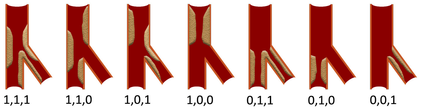 Fig. 1.
Schematic diagram of the Medina
classification. The three numbers respectively indicate whether there is
significant stenosis (
The complexity of CBLs varies due to factors such as the diameter of the stenosis, the length of the lesion, the bifurcation angle, the diameter of the vessels, and the specific pathology of MV and SB lesions. Individualized treatment strategies and optimization of techniques are key to ensuring the success of interventional treatment for CBLs. Currently, complex CBLs are defined according to the DEFINITION criteria [14, 15] (Table 1).
| Major criteria (For left main bifurcation): SB diameter stenosis |
| Major criteria (For non-left main bifurcation): SB diameter stenosis |
| Minor criteria: Greater than mild calcification; |
| Major criteria: Multiple lesions; |
| Major criteria: Bifurcation angle |
| Major criteria: MV reference diameter |
| Major criteria: Thrombus-containing lesions; |
| Major criteria: MV lesion length |
| A complex lesion was defined as meeting one of the major criteria plus 2 of the minor criteria. |
Notes: MV, main vessel; SB, side branch.
In the selection of interventional treatment strategies for CBLs, predicting the
risk of SB occlusion is one of the key challenges faced by operators. The Visual
Risk Prediction of Side-branch Occlusion in Coronary Bifurcation Intervention
(V-RESOLVE) scoring system can assess the risk of bifurcation occlusion [16, 17].
This scoring system takes into account various risk factors of different degrees,
with a V-RESOLVE score of
| Risk factors | Level | Point |
| MV TIMI flow grade before stenting | TIMI 3 | 0 |
| TIMI 2 | 6 | |
| TIMI 1 | 11 | |
| TIMI 0 | 17 | |
| Plaque distribution | at the opposite side of SB | 0 |
| at the same side of SB | 1 | |
| Pre-procedural diameter stenosis of bifurcation core (%) | 0 | |
| 2 | ||
| 3 | ||
| Diameter stenosis of the SB before MV stenting (%) | 0 | |
| 4 | ||
| 6 | ||
| 7 | ||
| Bifurcation angle (°) | 0 | |
| 4 | ||
| 6 | ||
| Diameter ratio between MV/SB | 0 | |
| 2 | ||
| 6 | ||
| 9 |
Note: SB, side branch; TIMI, thrombolysis in myocardial infarction; MV, main vessel; V-RESOLVE, Visual Risk Prediction of Side-branch Occlusion in Coronary Bifurcation Intervention.
By retaining the SB guidewire during the release of the MV stent [18], it aims to provide a pathway for subsequent rescue operations on the SB [19]. If the SB flow becomes compromised, this wire may serve as a guidewire to facilitate balloon or stent recrossing into the SB ostium. However, it cannot effectively prevent compression or obstruction of the SB ostium, which may occur due to plaque shift or carina shift toward the SB during MV stent expansion [20].
An undeployed balloon is pre-positioned in the SB. Following MV stent deployment, the SB balloon is inflated at low pressure (4–6 atm) to maintain ostial patency and subsequently withdrawn. This technique reduces plaque shift through its physical barrier effect, provides a landmark for SB wire re-entry, and significantly mitigates the risk of acute SB occlusion, establishing it as the superior branch protection strategy in CBLs interventions [21, 22].
Rewire technique refers to the critical procedural step of re-crossing a guidewire through the stent cell into the true lumen of the SB after the deployment of the first stent (either in the MV or SB). In CBLs interventions, this technique is pivotal for dual-stent strategies (e.g., Culotte, Crush, double-kissing crush (DK-crush)), directly influencing SB patency and long-term clinical outcomes [23].
POT is a critical approach in the treatment of CBLs [3, 24]. During the procedure, a non-compliant balloon shorter than the proximal stent coverage is employed, with a diameter matching the proximal reference vessel in a 1:1 ratio [24]. The balloon is then inflated to ensure optimal stent apposition. POT significantly facilitates the passage of branch guidewires and balloons by correcting inadequate stent apposition in the pMV segment, preventing subsequent guidewires from passing beneath the stent and promoting stent strut separation at the branch ostium. Key considerations for POT implementation include: (1) Balloon length should cover the entire pMV stent segment. If the balloon is too short, the procedure must be performed in multiple steps. (2) The length must not exceed the pMV stent segment to avoid proximal stent edge dissection. (3) The distal shoulder of the balloon should be positioned just proximal to the carina [23]. Overly proximal placement may result in insufficient stent expansion in the carina region, while overly distal placement risks carina shift.
KBI is a pivotal technique in the interventional management of CBLs, particularly when both MV and SB require intervention [5, 25]. By simultaneously inflating balloons in the MV and SB to create a “kissing” configuration at the bifurcation core, KBI offers several mechanistic advantages [21, 26]: (1) optimizing stent apposition to minimize strut coverage over the SB ostium; (2) correcting MV stent deformation caused by SB compression during branch dilation; (3) reducing the risk of SB occlusion caused by plaque shift/carina displacement.
When coronary angiography (CAG) identifies CBLs, the lesion is first classified
as either a false or true bifurcation according to the Medina classification
[10, 11]. For false CBLs, the preferred treatment strategy is PCI with provisional
stenting (PS). In cases of true CBLs, risk stratification is performed using the
DEFINITION criteria [15]. For simple CBLs, PS remains the recommended approach
[24]. However, for complex CBLs, dual-stent techniques are preferred [20]. The
selection of the specific dual-stent technique depends on the anatomical
characteristics of the bifurcation: (1) T stenting or T-stent and small
protrusion (TAP) is recommended when the angle between the MV and SB exceeds
70° [27]. (2) The Culotte stenting is preferred when the angle
is
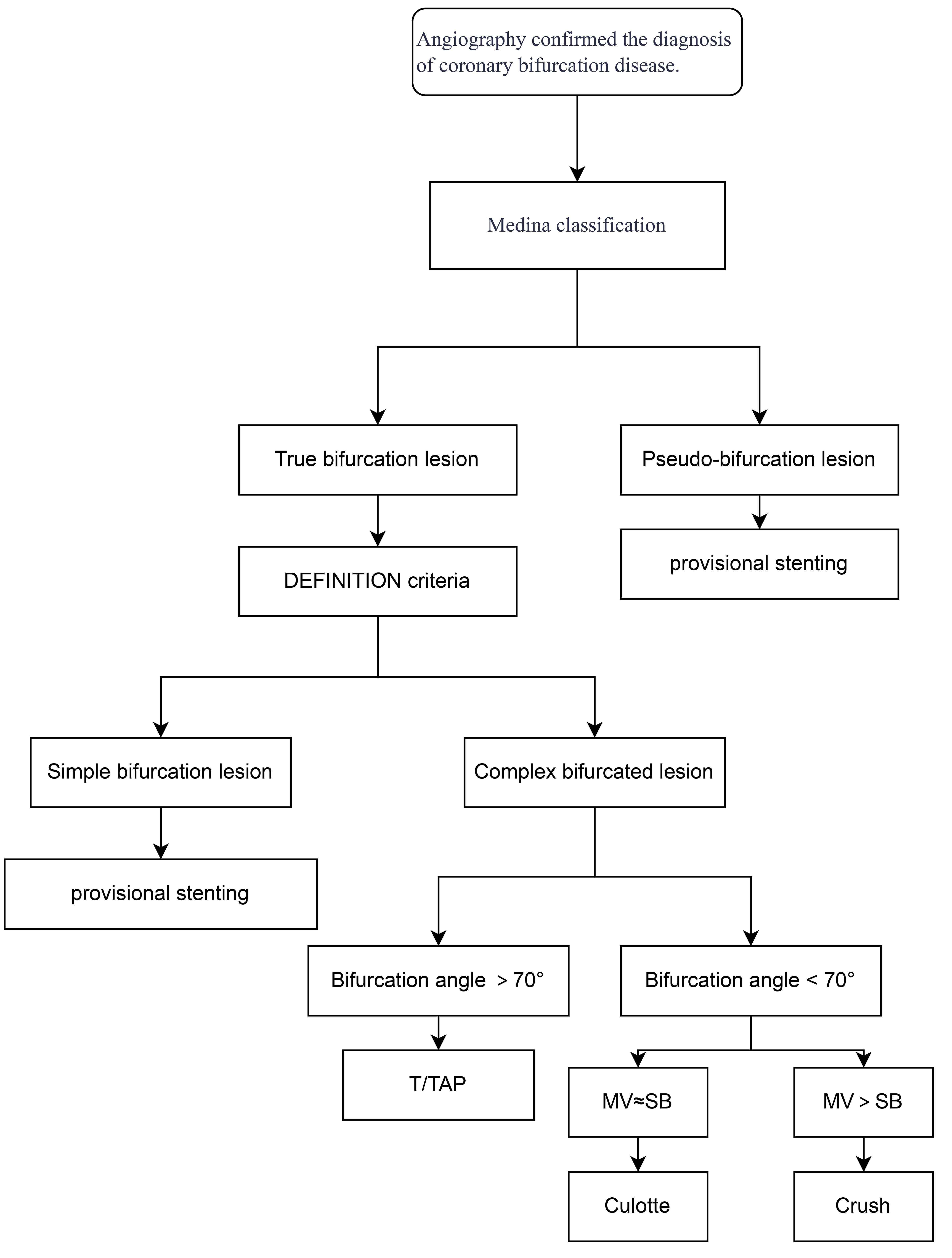 Fig. 2.
Flow chart of technical selection. MV, main vessel; SB, side branch; TAP, T-stent and small protrusion.
| Technique | Advantages | Disadvantages |
| Provisional stent | 1. The operation is relatively easy. | 1. Plaque shift or carina shift. |
| 2. The operation time is relatively short. | 2. Risk of branch ostium occlusion and rewiring challenges. | |
| 3. It applies to the majority of lesions. | ||
| T stent | 1. Simplified procedure. | 1. Potential incomplete branch ostium coverage. |
| 2. Flexible branch stent positioning. | 2. Excessive protrusion increases carina length. | |
| 3. Minimal metal overlap. | 3. Requires precise protrusion length control. | |
| Crush | 1. Complete coverage of branch ostium. | 1. Recrossing challenge and low final KBI success rate. |
| 2. Immediate dual-branch opening reduces ischemia time. | 2. Triple stent layer overlap in the proximal main vessel increases malapposition risk. | |
| 3. It may lead to significant metal carina formation and stent malposition. | ||
| 4. Technically complex and time-consuming. | ||
| Culotte | 1. Optimal branch ostium coverage. | 1. Technically complex and time-consuming. |
| 2. Lowest stent displacement rate. | 2. Double stent layer overlap delays endothelialization. | |
| 3. Plaque shift or carina shift may result in guidewire crossing difficulty. | ||
| DK-crush/culotte | 1. Significantly improved final KBI success rate (nearly 100%). | 1. Complex procedural steps. |
| 2. Reduces metal overlap and improves stent strut apposition. | 2. Higher radiation exposure and contrast volume. | |
| 3. Lower restenosis and thrombosis risks. | 3. It still depends on the operator’s experience. |
Note: DK, double-kissing; KBI, kissing balloon inflation; CBL, coronary bifurcation lesion.
The provisional stenting procedure consists of the following steps: (1) MV stent implantation; (2) POT of the MV stent; (3) evaluation of SB compromise, with subsequent treatment if required. If branch intervention is needed, the following steps are performed: (4) rewire; (5) SB balloon dilation; (6) reassessment of SB compromise, with stent placement if necessary [28].
Challenges and optimization: (1) Plaque displacement (Fig. 3A). It
predominantly occurs in lesions with high-volume plaque burden in the pMV; (2)
Carina displacement (Fig. 3B). Through intravascular ultrasound (IVUS), it has
been found that carinae exhibiting a spiked morphology (“eyebrow sign”) serve
as reliable predictors of SB ostial injury following MV stent deployment;
Preventive approaches involve protective measures for high-risk SB (V-RESOLVE
score
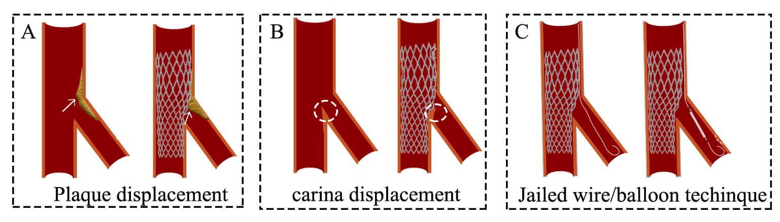 Fig. 3.
Challenges and optimization of the provisional stenting technique. (A) Plaque shift. (B) Carina displacement. (C) Jailed wire or jailed balloon technique. The white arrows represent plaque. The white circles represent the carina.
Following MV stenting, corrective measures are taken if SB outcomes are
suboptimal (thrombolysis in myocardial infarction (TIMI) flow
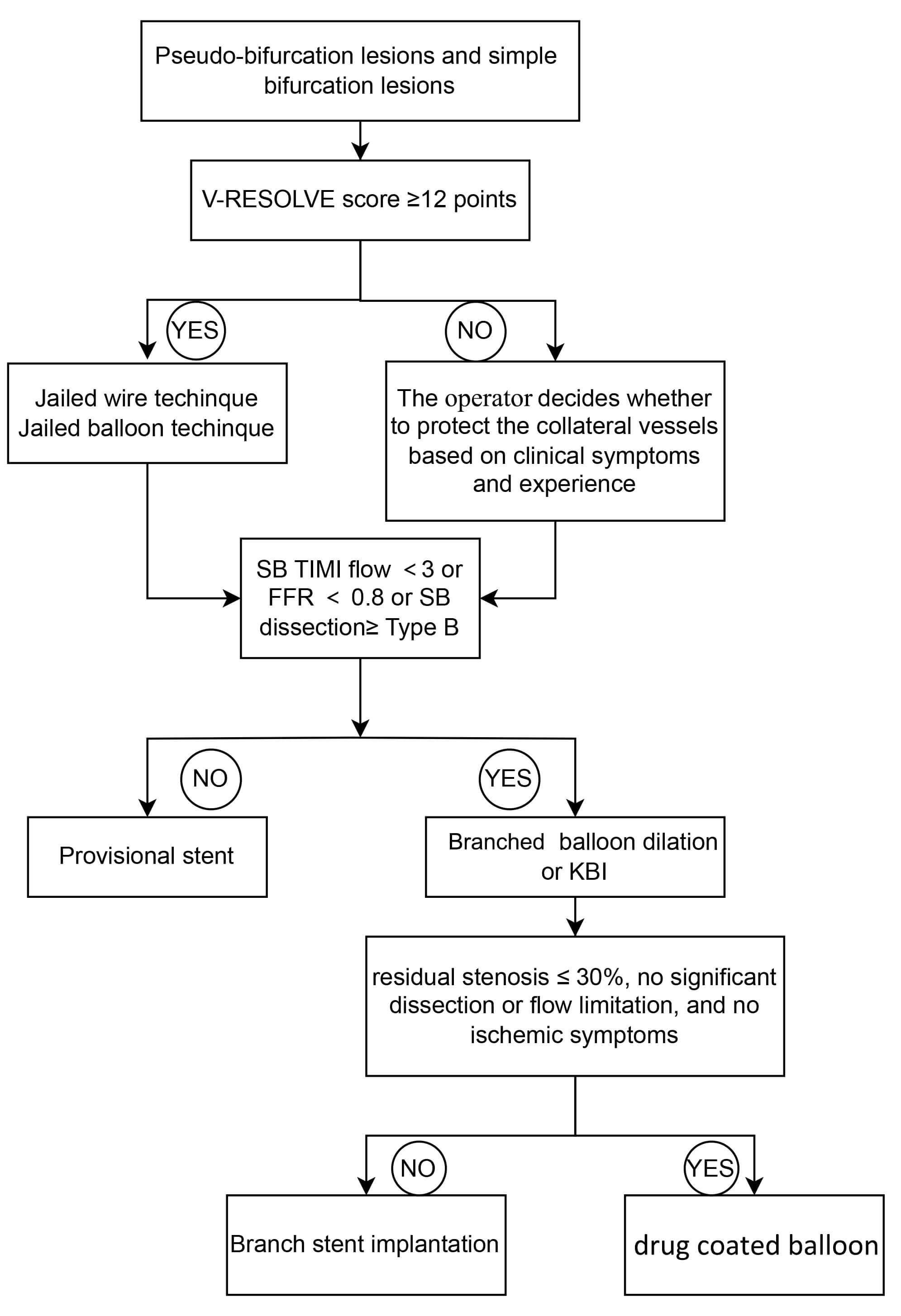 Fig. 4.
Flow chart of provisional stenting technique. SB, side branch; KBI, kissing balloon inflation; TIMI, thrombolysis in myocardial infarction; FFR, fractional flow reserve.
When the Angle between MV and SB is greater than 70°, the T-stent technique is selected (Fig. 5A). The T-stenting procedure involves sequential stent placement, beginning with the implantation of a stent in the SB, ensuring coverage of the SB lesion up to its ostium. Subsequently, a stent is deployed in the MV, followed by KBI to optimize stent apposition.
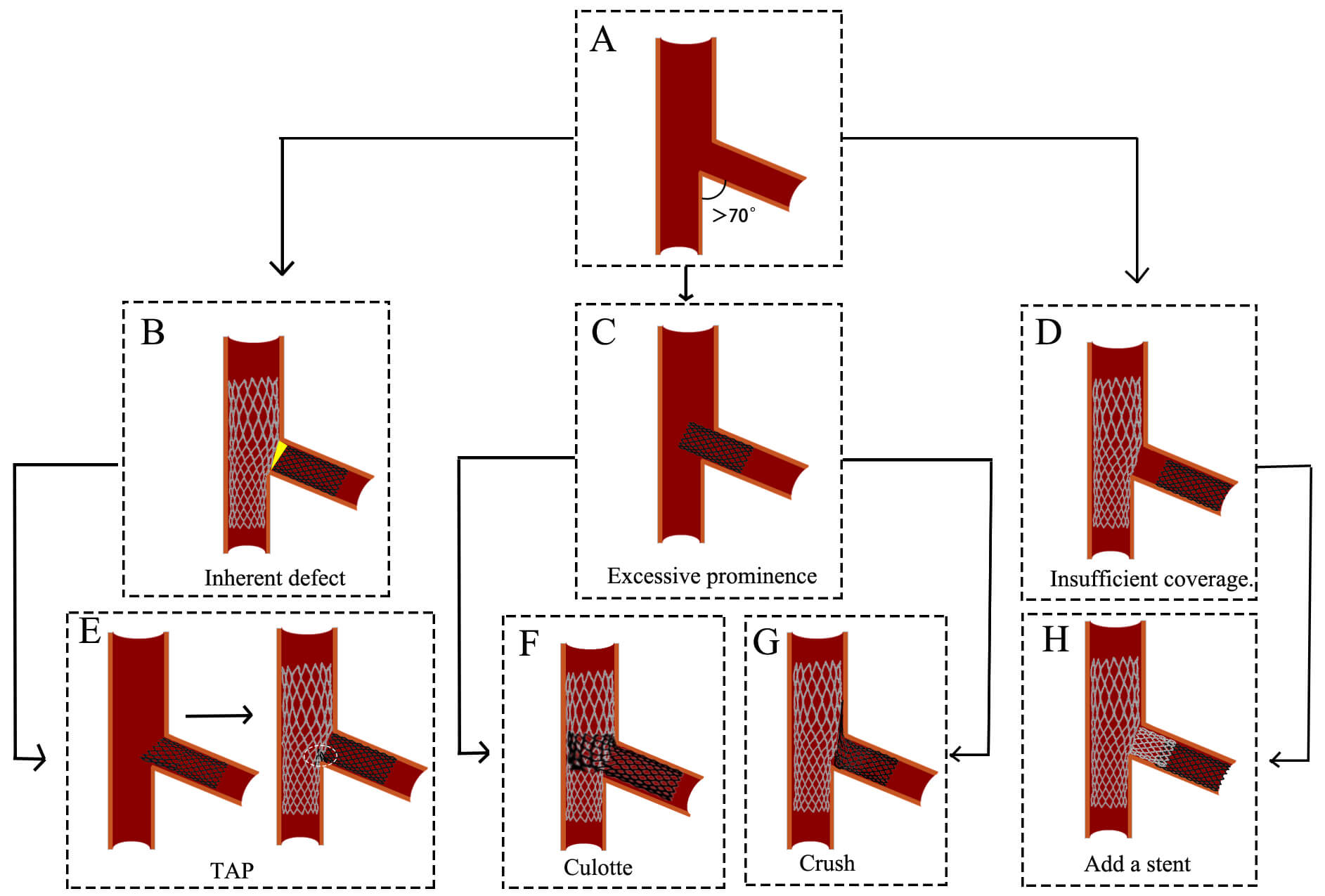 Fig. 5.
Challenges and optimization of the T stenting technique. (A)
The angle between MV and SB is greater than 70°. (B) The inherent defect
of the T stenting technique. (C) SB stent deployment
Challenges and optimization: However, a limitation of conventional T-stenting is
the frequent incomplete coverage of the SB ostium (Fig. 5B), which contributes to
a higher risk of restenosis [27]. To address this issue, the TAP is developed as
an optimized approach. In TAP, the proximal edge of the SB stent is intentionally
positioned 1–2 mm into the MV, forming a “T” configuration upon deployment
[30] (Fig. 5E). This modification ensures complete coverage of the SB ostium.
However, TAP introduces a new carina (Fig. 5E), which may influence hemodynamics.
Both T-stenting and TAP require precise stent positioning in the SB.
Misplacement, whether proximal or distal, can necessitate alternative strategies:
(1) If the SB stent is placed proximally (Fig. 5C) and the MV diameter is similar
to the SB (MV
When the angle between MV and SB is less than 70° and they are not equal, the Crush technique is selected (Fig. 6A). The Crush stenting technique involves the simultaneous placement of guidewires in both the MV and SB, followed by stent positioning along each guidewire. The proximal end of the MV stent is positioned to overlap the proximal end of the SB stent. The SB stent is deployed first (approximately 2 mm protrudes into MV), followed by MV stent deployment, which crushes the SB stent against the vessel wall. The guidewire is then advanced through the stent cell into the SB, and balloon dilation is performed to optimize stent expansion, ending up with a final KBI [24].
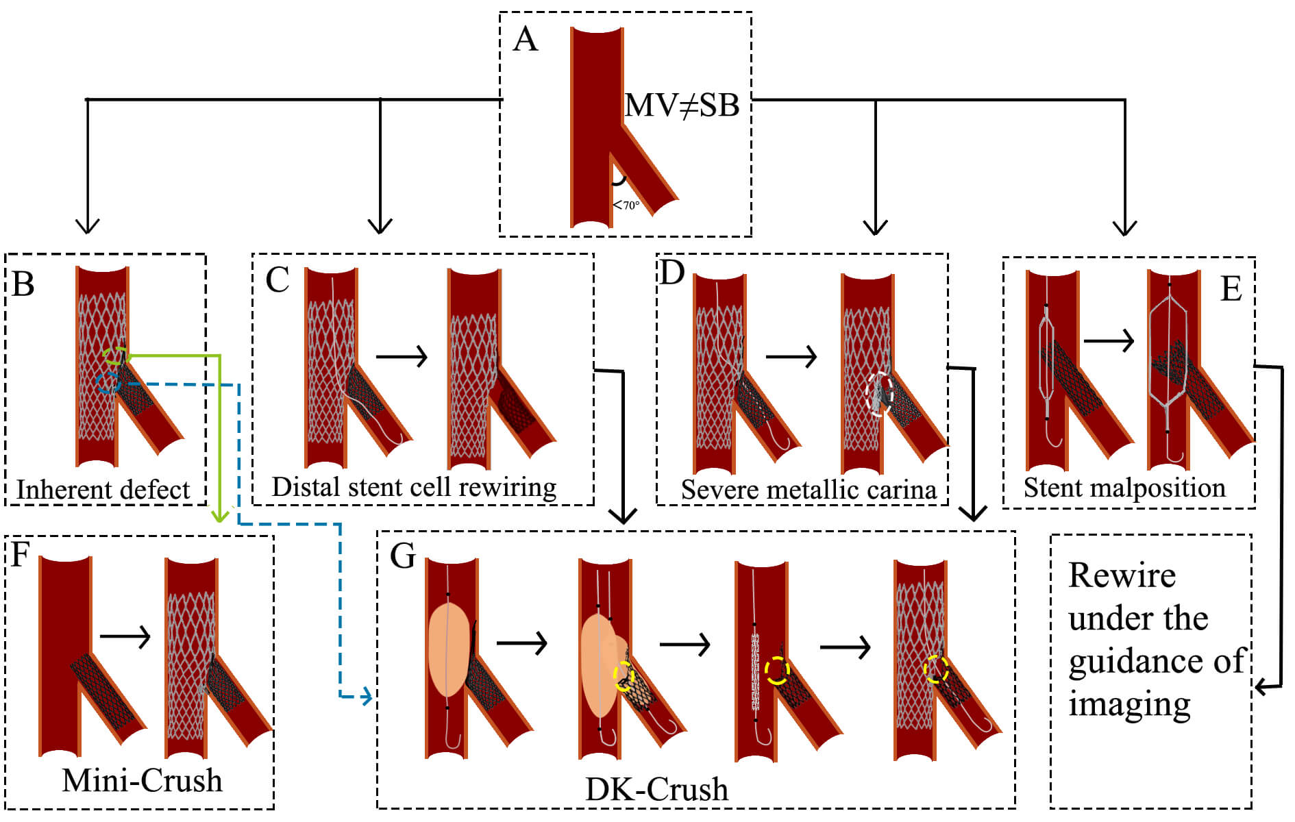 Fig. 6.
Challenges and optimization of the Crush technique. (A) The angle between MV and SB is less than 70°, and they are not equal. (B) The inherent defect of the Crush technique. (C) The wire is passed through the distal stent cell. The subsequent KBI resulted in stent deformation and incomplete lesion coverage. (D) The wire is passed through the proximal stent cell. The subsequent KBI results in the formation of a severe metal carina. (E) The direction of the stent is not controlled during balloon expansion. (F) A brief process of the Mini-Crush technique. (G) A brief process of the DK-Crush technique. The white circle indicates severe metallic carina. The yellow circles represent a single metallic layer. MV, main vessel; SB, side branch; TAP, T-stent and small protrusion; KBI, kissing balloon inflation; DK, double-kissing.
Challenges and optimization: (1) Stent strut overlap and apposition: The triple-layer stent strut overlap in the MV (Fig. 6B) may result in incomplete stent apposition, increasing thrombosis risk. The Mini-Crush technique minimizes this issue by limiting SB stent protrusion into the MV to 1–2 mm, ensuring complete ostial coverage while reducing metal overlap [32, 33] (Fig. 6F). (2) Rewiring difficulty and low KBI success rate: Rewiring through two stent layers (Fig. 6B) increases procedural complexity and may reduce KBI success, elevating risks of stent thrombosis and in-stent restenosis (ISR). The DK-Crush technique addresses this by performing the first KBI before MV stent implantation, leaving only a single stent layer at the SB ostium and facilitating rewiring [34] (Fig. 6G). The DKCRUSH-I trial demonstrated that final KBI was successfully achieved in 100% of cases using the DK-crush technique, compared to only a 75% success rate in conventional crush technique cases [35]. (3) Suboptimal guidewire passage and stent deformation: Guidewire passage outside the intended stent struts (between the SB stent and vessel wall) can distort stent architecture and compromise lesion coverage [36] (Fig. 6C). The DK-Crush approach emphasizes wire recrossing through the proximal stent struts during initial KBI, minimizing gaps at the ostium [37] (Fig. 6G). (4) Strut malapposition and delayed endothelialization: If the guidewire enters the SB through the proximal stent struts after MV stent deployment, subsequent KBI may elongate metal struts, delay endothelialization, and induce SB stent malapposition (Fig. 6D). The DK-Crush technique resolves this by recrossing the non-distal struts during the second KBI, promoting symmetrical stent expansion and improving strut coverage [34] (Fig. 6G). (5) Unpredictable stent compression direction: The direction of SB stent compression during crushing is often difficult to control (Fig. 6E). Intravascular imaging is recommended to guide precise rewiring and optimize stent positioning.
When the angle between MV and SB is less than 70° and they are nearly equal, the Culotte technique is selected (Fig. 7A). The Culotte stenting technique begins with the implantation of a stent in the SB, with its proximal end extending into the MV. The guidewire is then passed through a distal cell of the SB stent into the distal MV, followed by balloon dilation to expand the stent cell. In the MV, the second stent is subsequently deployed to fully cover both proximal and distal lesions. Finally, the guidewire is recrossed through a distal cell of the MV stent into the SB, where high-pressure balloon dilation and KBI are performed to optimize stent apposition [24].
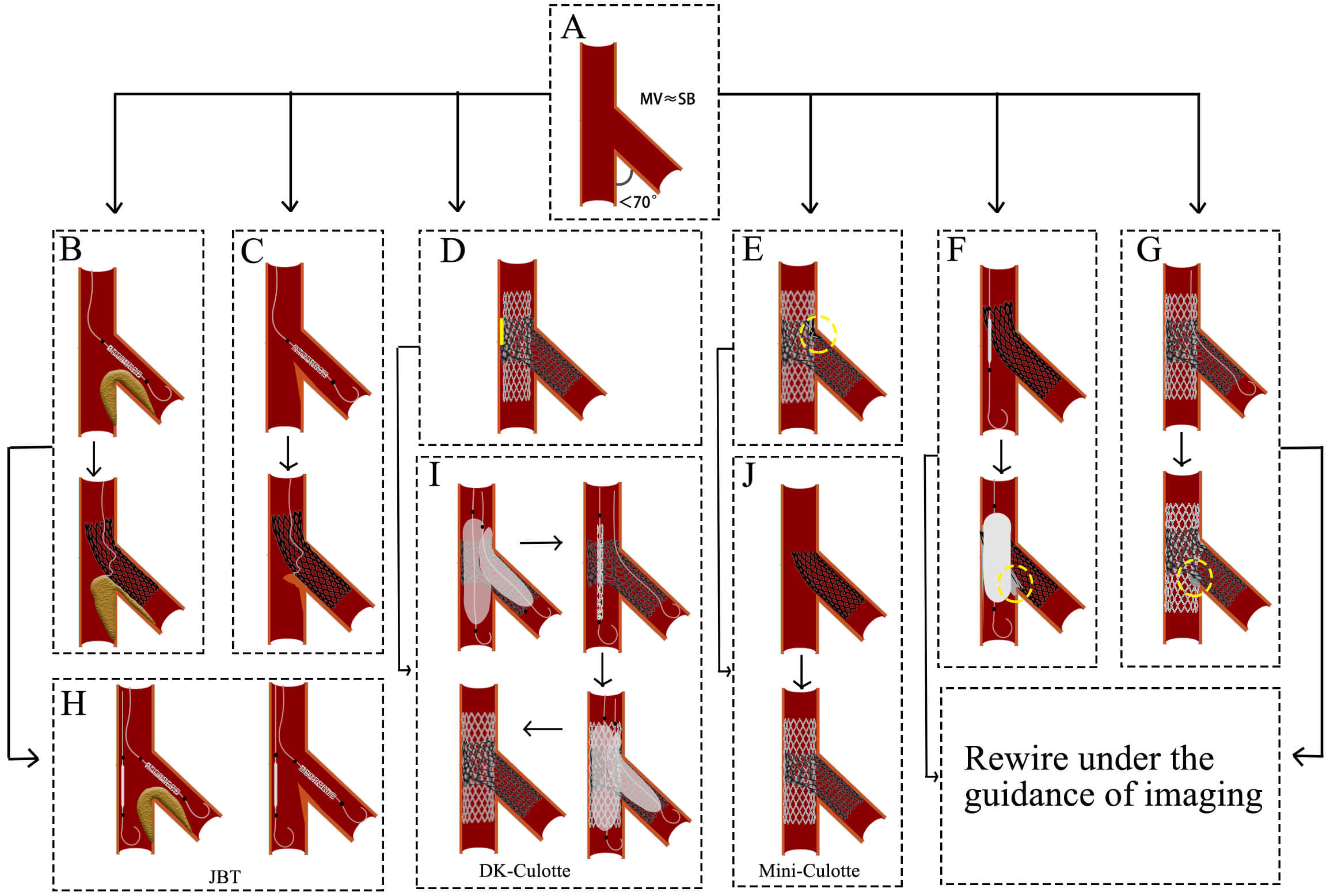 Fig. 7.
Challenges and optimization of Culotte technique. (A) The angle between MV and SB is less than 70°, and they are nearly equal. (B) The plaque shift impedes distal cell rewiring. (C) The carina displacement impedes distal cell rewiring. (D) The MV stent expansion is constrained by the SB stent rings. (E) The MV contains dual layers of stents. (F) The wire is passed through the proximal stent cell. Subsequent balloon expansion results in the formation of a severe metallic carina. (G) The wire is passed through the proximal stent cell. The subsequent KBI resulted in the formation of a severe metallic carina. (H) A protective balloon is implanted in the MV before the SB stent is expanded. (I) A brief process of the DK-Culotte technique. (J) A brief process of the Mine-Culotte technique. The yellow square in (D) indicates poor adherence of the stent. The yellow circle in (E–G) indicates severe metallic carina. MV, main vessel; SB, side branch; JBT, the jailed balloon technique; KBI, kissing balloon inflation; DK, double-kissing.
Challenges and optimization: (1) The guidewire needs to cross through the stent cells twice. Crossing through the proximal cell and the subsequent balloon expansion may lead to the formation of a metallic carina (Fig. 7F,G), requiring the operator to possess proficient wire-manipulation skills. (2) After SB stent deployment, plaque shift (Fig. 7B) or carina displacement (Fig. 7C) may exacerbate MV stenosis and impede distal cell rewiring. Pre-embedding a protective balloon in the MV (Fig. 7H) allows immediate lumen restoration upon rewiring failure. (3) The SB stent rings may constrain MV stent expansion, leading to poor adhesion of the stent to the vascular wall (Fig. 7D). The degree of MV stent expansion is determined by the SB stent rings. The DK-Culotte modification addresses this through dual KBI (Fig. 7I), ensuring optimal stent expansion and alignment [38, 39]. A bench study demonstrated that the DK Culotte technique optimizes stent apposition through sequential KBI [40]. (4) Dual-layer stent overlap in the MV increases the risk of restenosis (Fig. 7E). The mini-Culotte technique (Fig. 7J) minimizes stent overlap, reducing vessel irritation and restenosis potential [41].
DCB is an angioplasty device coated with antiproliferative agents (e.g.,
paclitaxel, sirolimus) that transfers the drug to the vessel wall during balloon
inflation, inhibiting vascular smooth muscle cell proliferation and migration to
reduce restenosis. DCB has emerged as an attractive alternative strategy for
treating coronary ISR, small vessel disease, and CBLs [42]. Particularly in small
vessel lesions with diameters
| Category | Specific considerations. |
| Severely calcified lesions | May impair balloon expansion or drug effect (requires adjunctive plaque modification techniques). |
| High-risk vessels | Ostial angle |
| Severe vessel tortuosity/angulation; | |
| Heavy thrombus burden. | |
| Flow-limiting | Persistent slow-flow or TIMI flow |
| Others | Hypersensitivity to coating drugs (e.g., paclitaxel/sirolimus). |
Note: TIMI, thrombolysis in myocardial infarction; DCB, drug-coated balloon.
Challenges and optimization: (1) Before DCB angioplasty, the desired outcomes of
lesion preparation include residual stenosis
The conventional assessment of CBLs predominantly relies on CAG. However, PCI for CBLs typically requires more complex stent implantation techniques and is associated with higher risks of mortality, myocardial infarction, and repeat revascularization compared to non-CBLs. Sole reliance on CAG has inherent limitations, including suboptimal evaluation of lesion characteristics and stent implantation outcomes [47].
The 2024 European Society of Cardiology (ESC) Guidelines for the Management of Chronic Coronary Syndromes have assigned a Class IA recommendation for IVUS and optical coherence tomography (OCT) guidance in PCI for true CBLs [48]. These imaging modalities play a pivotal role in optimizing stent sizing, assessing plaque distribution, guiding wire recrossing, and confirming stent apposition. Thereby, it significantly reduces the risk of post-procedural cardiovascular adverse events. The OCTOBER trial demonstrated that OCT-guided PCI significantly reduced 2-year MACE compared with angiography-alone guidance (10.1% vs. 14.1%, HR = 0.70, p = 0.035), with particular advantages in minimizing branch occlusion and stent thrombosis. Similarly, the ULTIMATE trial’s 3-year follow-up showed significantly lower target vessel failure in the bifurcation subgroup with IVUS guidance (HR 0.48, 95% CI: 0.27–0.87) [49]. The 5-year outcomes from DKCRUSH-II revealed reduced myocardial infarction rates in patients undergoing IVUS assessment (1.8% vs. 5.4%; p = 0.043) [50].
From a technical perspective, IVUS provides quantitative assessment of plaque
burden (
Functional assessment of CBLs has emerged as a pivotal tool for precision
interventional decision-making by quantifying hemodynamic impairments, overcoming
the anatomical limitations of conventional angiography [53]. Its fundamental
value lies in accurate ischemia risk stratification: FFR measurements reveal that
72% of SB with
Recent innovations in interventional cardiology are revolutionizing treatment strategies for CBLs. Bioresorbable scaffolds have emerged as a promising option, offering complete biodegradation, restoration of vasomotion, and reduced long-term inflammatory responses from permanent metallic implants [59]. Clinical studies have demonstrated favorable outcomes when applying Bioresorbable scaffolds to CBLs. The BioMime™ Branch sirolimus-eluting coronary side-branch stent features a unique design with four radiopaque markers [8]: proximal/distal markers, side-branch ostium marker, and carina marker. It has garnered increasing attention. Additionally, the R-One robotic system for PCI is gaining traction [9]. While requiring further clinical validation, these technologies represent significant advances toward personalized, physiology-guided treatment approaches. With accumulating evidence, these innovations may establish new paradigms for precision therapy of CBLs.
CBLs remain a challenging area in PCI. This complexity stems from both
anatomical heterogeneity, intricate procedural considerations and long-term
clinical outcomes. This review systematically examines current key techniques,
strategy optimization approaches, and individualized management paradigms for
CBLs, incorporating advances in functional assessment and intravascular imaging.
Initially, procedural strategy selection constitutes the core challenge. The
single-stent strategy (e.g., provisional stenting) is preferred
for pseudo-bifurcation lesions due to procedural simplicity. However, its risk of
SB occlusion cannot be overlooked, particularly in high-risk patients (V-RESOLVE
score
The treatment of CBLs remains challenging due to issues like plaque shift, stent strut obstruction, and incomplete stent apposition. Current strategies rely on Medina classification, DEFINITION criteria, and V-RESOLVE scoring to guide individualized approaches. Key techniques include precise lesion localization, accurate rewiring, and dual kissing balloon inflation under intravascular imaging guidance, which enhance procedural success and long-term outcomes while minimizing complications. However, real-world application requires clinical flexibility, as optimal management continues to evolve and demands operator expertise in adapting to specific lesion characteristics.
CBL, coronary bifurcation lesion; PCI, percutaneous coronary interventions; MACE, major adverse cardiovascular events; pMV, proximal main vessel; dMV, distal main vessel; MV, main vessel; SB, side branch; V-RESOLVE, Visual Risk Prediction of Side-branch Occlusion in Coronary Bifurcation Intervention; DK-crush, double-kissing crush; JWT, jailed wire technique; JBT, jailed balloon technique; POT, proximal optimization technique; KBI, kissing balloon inflation; PS, Provisional stenting; TAP, T-stent and small protrusion; ISR, in-stent restenosis; DCB, drug-coated balloon; ISR, in-stent restenosis; CAG, coronary angiography; IVUS, intravascular ultrasound; OCT, optical coherence tomography; TIMI, thrombolysis in myocardial infarction; FFR, fractional flow reserve; iFR, instantaneous wave-free ratio; RFR, resting full-cycle ratio; QFR, quantitative flow ratio.
XA, ZLQ, QF, ZDJR, WPZ, HL, XYL, CYF and LND conceived this study; XA, ZLQ, QF, ZDJR, WPZ, HL, XYL, CYF and LND performed literature searching, literature removal, quality assessment and literature classification. XA, ZLQ and QF summarized and sorted out the parts of the content provided by all authors, and finally completed the writing of this article. All authors contributed to writing or revising the manuscript. All authors read and approved the final manuscript. All authors have participated sufficiently in the work and agreed to be accountable for all aspects of the work. QF is the corresponding author. XA and ZLQ are co-first authors.
Not applicable.
Not applicable.
The Liaoning Province Science and Technology Foundation of China (2023-MSLH-127); the Shenyang Science and Technology Bureau of China (22-321-33-49).
The authors declare no conflict of interest.
Publisher’s Note: IMR Press stays neutral with regard to jurisdictional claims in published maps and institutional affiliations.