


 , M.U. Jurczyk 2
1 Department of Electroradiology, University of Medical Sciences, St. Garbary 15, Poznan, Poland
2 Department of Maternal and Child Health, University of Medical Sciences, St. Polna 33, Poznan, Poland
Abstract
Objective: Hysterosalpingography (HSG) is based on the administration of a shading agent to the uterine cavity and fallopian tubes using a Schulze apparatus. An X-ray beam (X) is then directed at the abdominal area of the patient and diagnostic images are obtained for evaluation. The radiation beam and its mode of administration have a decisive influence on the radiation dose to which the patient is exposed. The aim of this study was to determine the physical parameters of this exposure in such a way that the dose distribution during the HSG examination was the most beneficial for the patient. Materials and Methods: Measurements to evaluate the effect of exposure parameters on the quality of radiological images obtained during HSG in slim and obese patients were made in 216 repetitions of the standard HSG test. Additional research data was obtained from measurements made in the X-ray laboratory at the Clinical Hospital. Results: The comparison of all measurements made for experimental models simulating a slim and obese patient demonstrated that the dose distribution most advantageous for the patient is obtained for pulsations of an X-ray tube for PPS = 6, regardless of the thickness of the patient. Conclusions: The image quality and size of the radiation dose received during the HSG examination depends on the individual characteristics of the patient. During the measurements performed in order to compare the exposure conditions set by the automatic exposure control (AEC) system and the resulting dose, this study demonstrated that the dose distribution most advantageous for the patients is obtained for pulsations on an X-ray tube for PPS = 6, regardless of the thickness of the patient.
Keywords
- Hysterosalpingography
- DAP radiation dose
- Exposure parameters
Hysterosalpingography (HSG) is an imaging method used in the diagnosis of female infertility. The HSG examination involves the administration of an iodine water-soluble contrast agent to the uterine cavity. During the examination, the doctor observes the flow of contrast on a live basis and carries out the examination in the form of documented X-ray images [1]. The result of the examination allows clinicians to recognize uterine malformations, possible obstruction of the oviducts or fistulas to neighboring organs [2, 3]. The size of the dose area product (DAP) received during the HSG examination is affected by the X-ray exposure time, beam length and the number of X-ray images taken. During the examination, the patient is exposed to potentially harmful effects of X-rays, so attention should be paid to physical parameters defining the intensity of the radiation beam emitted from the X-ray tube. Appropriate selection of exposure parameters minimizes the size of radiation dose administered to the patient during the examination. The size of the dose depends on the operator of the X-ray apparatus [4, 5] and even the smallest doses of radiation may increase the probability of cancer development in the future so these risks should be minimized [6].
In order to obtain good quality examination results while decreasing the size of the absorbed radiation dose, the physical parameters affecting the distribution of the radiation dose should be optimized [7-9]. Optimization of the exposure conditions is related to the patient’s anatomy and the area of the body to be examined. In order to obtain the lowest possible dose and concurrently the image of the highest quality, the voltage on the X-ray tube (kV), anode current intensity, and exposure time (mAs) should be carefully selected and the beam should be reduced to the minimum necessary for the size of the area to be examined. Additionally, a suitable dose of radiation in the X-ray tube should be selected, and automatic exposure control (AEC) in digital cameras should be used. The AEC system interrupts the exposure of radiation when the appropriate amount of radiation reaches the detector in this apparatus. This system directly affects the brightness and contrast of the image obtained on the monitor. The selection of the settings of ionization chambers used affects the dose size and the quality of diagnostic images obtained [10]. During an X-ray, which is used in the HSG examination, the value of the pulse exposure system (PPS) is also of great importance. This system is intended to extend the life of the X-ray tube, but above all to reduce the amount of radiation emitted toward the patient during the examination. It is therefore recommended to use the pulsed emission instead of a continuous beam. This protocol also allows the person performing the examination to see more detail in the images collected [11].
In clinical practice, DAP measurement is used during examinations with X-ray apparatus equipped with the AEC system. DAP expresses the product of the dose and area of the X-ray beam perpendicular to the axis of the beam. DAP can be measured directly using a meter mounted in an X-ray apparatus, so DAP enables a direct comparison of an effect of various physical factors set during the examination [12].
According to the guidelines included in the Announcement from the Minister of Health of November 10, 2015 on the publication of standard radiological procedures in the field of radiology, imaging diagnostics and imaging radiology, the following should be used during the HSG examination: an electronic imaging enhancer during scopy, when performing X-ray images-voltage of 70-80 kV and the lowest possible lamp current preventing the loss of valuable diagnostic information from the image [Ref]. During the scopy, the lamp voltage should have a value of 65-75 kV, the smallest possible lamp current and a pulse scopy, the value of which depends on the anatomical conditions of the patient. The aim of this study was the selection of physical parameters of exposure in such a way that the radiation dose distribution during the HSG examination was the most beneficial for the patient.
Measurements concerning an evaluation of the effect of applied exposure parameters on the quality of radiological images obtained during HSG in slim and obese patients were made in 216 repetitions of the complete standard HSG test. Research data was obtained from measurements made in the X-ray laboratory at the Clinical Hospital.
The examinations were not performed directly on patients but on water phantoms, which were designed to simulate the body of a slim and obese patient. The DAP dose measurements obtained during the simulated HSG test were made on the X-ray apparatus Precision RXi under exposure conditions determined by the AEC system and constant camera settings such as a large focus in the X-ray tube, active central ionization chamber in the AEC table, average density of the photo with a value of 1, OF distance 100 cm, anatomical program-pelvis (HSG), exposure time during a single scopy (10 seconds) using a Bucky type mobile anti-diffusion screen, a Fuji detector and a film size 35.6 × 43.2.
The same camera settings were used during all measurements, and the value of the PPS pulsed exposure system and exposure conditions, which were automatically set by the AEC system, were changed. The exposure conditions set by the camera allowed selection of the conditions individually for the phantom simulating the patient, which allowed the reduction of the radiation dose whilst obtaining the best radiological image for diagnostic evaluation [11, 13]. The following materials were used to assess the DAP dose for the patient during HSG examination: 13 cm water phantom (a container filled with water as a homogeneous medium) and a 26-cm water phantom (two containers filled with water placed on each other). Different thicknesses of the phantoms were designed in order to simulate a slim and obese patient.
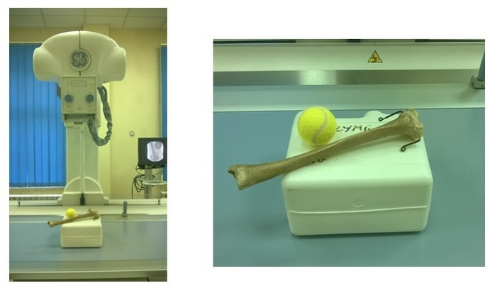
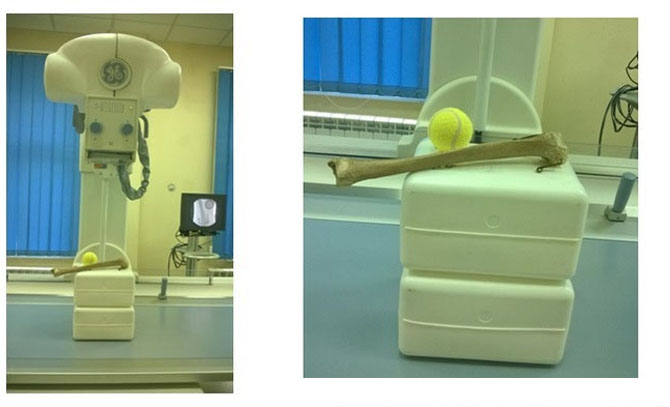
In order to evaluate the image contrast quality on the X-ray, the elements absorbing X-rays to a lower or higher degree than the surroundings were added to the water phantoms of various thicknesses (simulating slim and obese patients). Human tibia absorbed more than the water phantom itself and the tennis ball absorbed less because it was filled with air. Due to the introduction of these additional elements, the phantoms can be described as anthropomorphic phantoms (Figures 1 and 2).
 Figure 1.
— Water phantom with a thickness of 13 cm with elements absorbing X-ray to a higher and lower degree than the surroundings.
 Figure 2.
— Water phantom with a thickness of 26 cm with elements absorbing X-ray to a higher and lower degree than the surroundings.
A radiological image in the form of digital X-ray images obtained as a result of the examination was used to analyze an effect of exposure parameters on the quality of the radiographs obtained (Figure 3). An evaluation of the dose, measured as a DAP dose, was performed under conditions of the standard HSG examination, without complications. It was assumed that the examination consists of two scopies lasting ten seconds each and of the implementation of two X-ray images as test documentation. The conditions of the exposure were set by an X-ray apparatus using Automatic Exposure Control (AEC) system. The possibility of manual change of the size of PPS, the so-called pulsed exposure system, was investigated. In order to determine the exact detailed direction of measurements, the average DAP doses for a 13-cm thick phantom and for a 26-cm thick phantom at PPS from 1 to 25 was determined at the beginning. The results were obtained for 20 independent measurements.
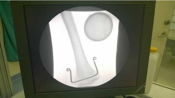 Figure 3.
— Radiographic image from the monitor seen during phantom screening.
The obtained results allowed comparison of the DAP dose, up to 13 cm thick water phantom simulating the patient, for all PPS values 1, 3, 6, 12, and 25 during the examination. Other exposure conditions were left unchanged. Table 1 shows the measured total amount of the DAP dose dependent on the PPS value for a 13-cm thick phantom. For a phantom simulating a slim patient, with PPS values of 12 and 25, the image was overexposed and unreadable, hence, these measurements were excluded from analysis in more detailed measurements.
| PPS | DAP [mGy*cm2] |
| 1 | 744 |
| 3 | 857 |
| 6 | 967 |
| 12 | 1083 |
| 25 | 1299 |
The DAP dose summed up for the radiation introduced into the 26 cm thick water phantom was also compared for all PPS values 1, 3, 6, 12, and 25 during the examination. Table 2 shows the measured total amount of DAP dose dependent on the PPS value for a 26-cm thick phantom. For a phantom simulating an obese patient, with PPS values of 1 and 3, the X-ray image was of low contrast, which would in practice lead to poor diagnostic quality. Thus, these measurements were excluded from analysis in more detailed measurements.
| PPS | DAP [mGy*cm2] |
| 1 | 6737 |
| 3 | 6271 |
| 6 | 6510 |
| 12 | 7147 |
| 25 | 8275 |
The implementation of the above initial measurements allowed the setting of exposure parameters regarding the quality assessment of the received image in combination with the DAP dose given during the examination. The following PPS values were used for both phantoms during subsequent measurements: 13 cm thick phantom → PPS = 1, 3, 6 (Figure 4) and 26-cm thick phantom → PPS = 6, 12, 25 (Figure 5).
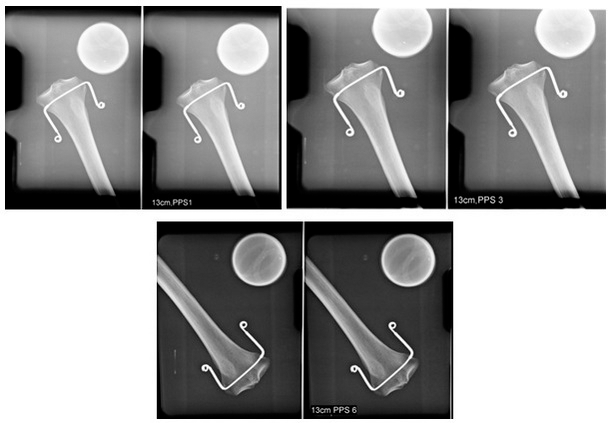 Figure 4.
— Comparison of radiograms obtained for 13-cm thick phantom for various PPS values = 1, 3, and 6.
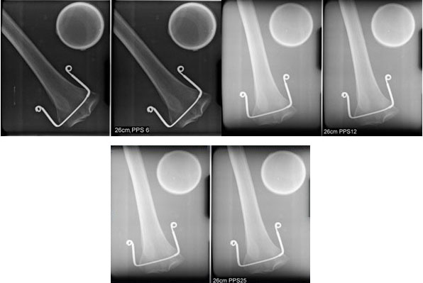 Figure 5.
— Comparison of radiograms obtained for 26-cm thick phantom for various PPS values = 6, 12, and 25.
The HSG examination procedure adopted during premeasurements for a 13 cm thick phantom was additionally repeated 36 times for each PPS value = 1, 3 and 6. Table 3 presents the average values from all measurements and the total DAP doses during the complete examination as well as the DAP dose per one X-ray image for a 13-cm thick phantom that simulated a slim patient. In particular for a phantom simulating a slim patient, the DAP dose obtained during the complete examination and during single X-ray image taking is clearly lower at PPS value = 6.
| PPS | Total averaged DAP dose [mGy*cm2] | Averaged DAP dose given during a single X-ray |
| 1 | 766 | 369 |
| 3 | 854 | 366 |
| 6 | 522 | 189 |
The HSG examination procedure adopted during premeasurements for a 26-cm thick phantom was additionally repeated 36 times for each PPS value = 6, 12, and 25. Table 4 presents the average values from all measurements and the total DAP doses during the complete HSG examination as well as the DAP dose per one X-ray image for a 26-cm thick phantom that simulated an obese patient. The best, i.e., the lowest DAP dose value for the phantom simulating an obese patient was obtained for the pulsation value PPS = 6. The radiological image obtained for this PPS value is the most useful in diagnostic evaluation. Therefore, it should be assumed that there is no need to expose the patient to an additional, much higher dose of X-ray radiation during the HSG examination. The comparison of all measurements made for phantoms simulating a slim and obese patient shows that dose distribution most advantageous for the patients is obtained for pulsations on an X-ray tube for PPS = 6, regardless of the thickness of the patient.
| PPS | Total averaged DAP dose [mGy*cm2] | Averaged DAP dose given during a single X-ray |
| 6 | 4547 | 1987 |
| 12 | 7095 | 2888 |
| 25 | 8281 | 2903 |
Many factors can affect the quality of radiological diagnostic images obtained during the HSG examination and attention should be paid to the size of radiation dose received by the patient during this procedure. Different levels of radiation can be determined depending on the diagnostic need. It is possible to determine the so-called DAP, which is the product of kerma in the air and the surface area of the X-ray beam perpendicular to the axis of the beam, as well as the input dose however this does not take into account diffuse radiation on the part of the patient and the surface input dose [12, 14]. The input dose enables the best determination of patients’ exposure to ionizing radiation when using different patient imaging techniques and is the basis for these comparisons. Measurement of this dose also allows one to calculate the absorbed dose, i.e., the dose received by the personnel performing the diagnostic test [15].
The input surface dose was proposed as a reference point in all radiological conventional diagnostic procedures and was adopted in the European Union thanks to European Directive 97/43/Euratom [16].
The quality of the image from the examination is directly affected by the exposure parameters, and the body weight of the patient is an important factor that affects this. Parameters such as the electric voltage of the X-ray tube [kV], the intensity of current applied to the lamp [mA], or the radiation exposure time [s], depend primarily on the size and thickness of the examined subject. The properly set initial exposure parameters affect the quality of the radiological image obtained, i.e., contrast and density, as well as the number of artifacts generated in the image. Increasing parameters such as the product of current intensity and exposure time [mAs] can improve the contrast on the radiological image, but unfortunately requires an increase in the dose of radiation that the patient receives [17, 18].
The quality of X-ray images should be optimized each time so that the patient is not exposed unnecessarily to too high a dose of radiation. The professional literature provides information on frequent abuse of the capabilities of digital X-ray equipment, due to the possibility of very high-quality images being obtained, although this quality is not always necessary for accurate diagnosis. The quality of the radiographic image should be adapted to the type of clinical procedure in order to obtain the required imaging quality with the lowest dose of radiation. Incorrect setting of image parameters can also contribute to reduced amount of diagnostic information due to the inferior quality of the examination result [9, 18, 19].
During the measurements used to formulate the conclusions in this study, all mentioned parameters were selected and set before the beginning of the examination, and then the digital AEC system was used to select exposure conditions such as voltage [kV] and exposure time [mAs]. The use of exposure automation allowed better optimization of the conditions used during the examination. The conditions for proper operation of the AEC system includes suitable calibration and correct positioning in relation to the examined object. An application of exposure automation instead of manual settings has no effect on image quality, but its effect on the size of the received dose is proven [7, 9, 16, 20]. Reference levels have been introduced for particular types of examination, that optimized the examination conditions as well as protecting the patient, taking into account the preparation and selection of the type of examination, the type of body part being examined, the thickness of the patient and kind of equipment used for imaging [21].
The image quality and size of the radiation dose received during the examination depend on the individual characteristics of the patient [17, 22]. During the measurements performed in this study the exposure conditions set by the AEC system and the resulting dose considered both the slim and obese patient. Optimal selection of exposure conditions is unfortunately not always respected and often the patient is exposed to an additional dose of radiation associated with the need to repeat the examination in order to improve the quality of the diagnostic image to obtain additional clinically relevant information. In conclusion, the size of the radiation doses that patients receive are very diverse and result from the poorly described techniques being used, including the body type and area being examined. Frequency of scopy pulsation should be selected for the type of examination and for the needs of the procedure being performed during its execution, so that the radiation dose can be reduced to a minimum for both the patient and the staff performing the examination [17, 23].
Diagnostic image quality and size of the radiation dose received during the HSG examination depend on the individual characteristics of the patient. During the measurements performed in order to compare the exposure conditions set by the AEC system and the resulting dose, it was necessary to consider the slim and obese patient.
Thanks to all the peer reviewers and editors for their opinions and suggestions.
The authors declare no conflict of interest.